Prompt:
Create a system that oscillates units such that one can periodically check wire connectivity within with a digital multimeter
Constraints:
To Run 6 units together
To Run 750,000 cycles within 2 weeks
Challenges:
Incorporating adjustable parameters
OLIVER Design Flow
Outline
July 2022 - December 2022
Precedent:
A previous employee had been given this same task before it came to me so I first looked at their schematic before starting. Their testing system consisted of DC stepper motors fixed to 80/20 bars that were clamped onto a shelf. These motors would slowly oscillate their respective units which rested on the shelf layer below. The entire system was connected to an electrical system that none of my team could understand and the code used was missing. Overall, I couldn't adjust the speed nor the angle of oscillation for this system and it all ran under one counter so if one unit stopped working, the counter would completely ignore this.
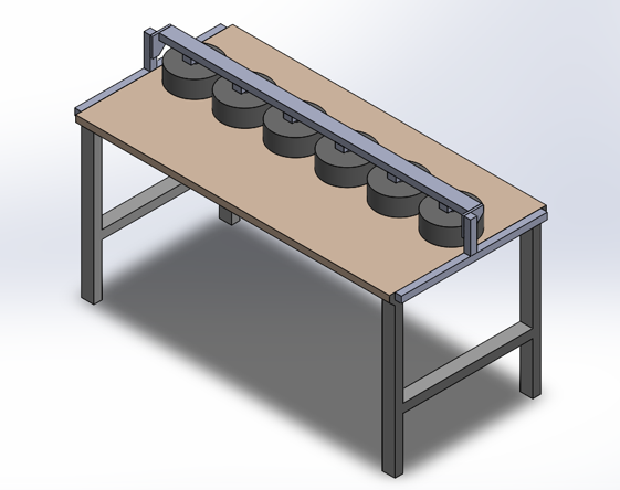
OLIVER I followed the same "two units per shelf-layer" format as the precedent, but needed more adjustable parameters and better support.
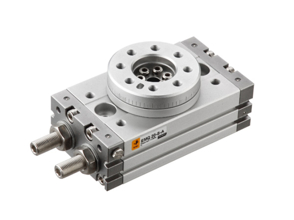
Regarding the angle of oscillation, the DC motors were switched out with rotary pneumatic cylinders (RPCs) as seen on the left. These are angle adjustable through turning the bolts on the sides. A network of pipes with air flow controller valves were connected such that air pressure adjustments could also be made for each unit as well as the entire system.
The circular face of the RPC was drilled concentric to the top of a unit and the base of the RPC was drilled into the shelf above. Each unit base was fixed to the shelf it rested on with carpet tape to ensure minimal movement.
OLIVER I
Angles and Boosting Support
Rotation Rate
Electrical: Circuit
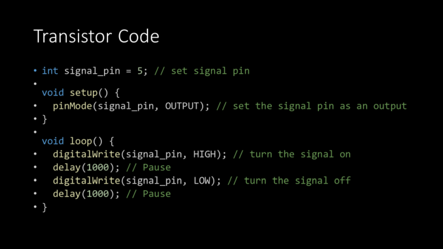
Electrical: Arduino Code
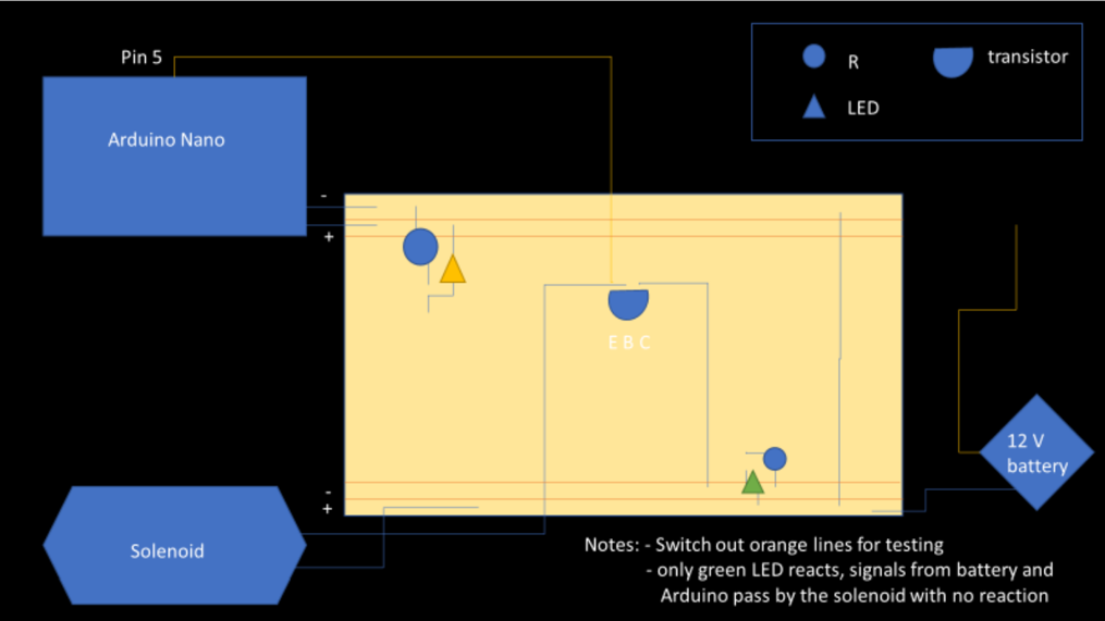
Regarding the speed, the main air pipe from the pressure source was connected to three different solenoids, each connected to two units via piping. The solenoids were connected to an Arduino Uno. Below is the initial circuit and code for the first iteration of OLIVER. Through adjusting the delays in the loop, each solenoid's HIGH/LOW switch timings could be adjusted, thus allowing for the oscillation speeds to change.
Counter
To ensure each unit was accounted for, each was assigned a magnet-proximity sensor with a digital display. A magnet was fixed to the unit's top and the sensor was positioned above where the magnet passed halfway through it's pass when the unit oscillated to avoid multiple counts. Thus, the number on the display would have to be halved for accurate cycle readings.
Conclusions
Successes:
Created functional system that gathered required data in set time
System was easily adjustable in both angle and speed of oscillation
Needs Improvement:
Since the units were drilled into the RPCs and the RPCs were drilled into the shelves, it made it difficult to troubleshoot and adjust units as essentially everything would have to be taken apart each time.
OLIVER II
OLIVER II was made later when new parameters had to be tested. Thanks to documentation, it was easily to rebuild a large part of OLIVER I, but some improvements were implemented.
Modularity
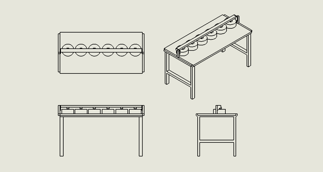
The main issue with OLIVER I was it's difficulty to adjust and switch out units. Thus, OLIVER II went back to the 80/20 foundation, this time using one bar running across a table. Thus if you wanted to adjust a unit, you could just loosen the screws at the top that went through the bar into the RPCs. However, taking out entire units still proved to take more time than desired. Thus, I designed and printed the RPC attachment below in SOLIDWORKS:
RPC Attachment
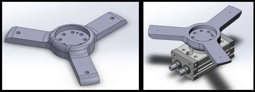
This made it such that, instead of drilling the circular face of the RPC into the unit, the three holes on the prongs of the attachment were drilled into the unit instead. This made it such that, if I wanted to detach a unit, I could simply unscrew the bolts from the top of the unit and slide it out.
Other Improvements
A pressure gauge was added at the air source to ensure repeatable pressure readings were being pushed through the entire system.
OLIVER II CAD